re you ready to hit the airwaves and add Bluetooth to your project? With the BlueSMiRF and Bluetooth Mate line of products, you’re much closer than you think to replacing those pesky, tangled RX and TX wires with 2.4GHz wireless communication.

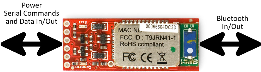
Each of these modules has a Bluetooth transceiver on it, meaning they’re capable of both sending and receiving data. They’re perfect for directly replacing a wired asynchronous serial interface. Free of wires, your devices can be up to 100 meters away (RN41 Gold) from each other. On top of those benefits, these modules are also very easy to use. There’s no messing with Bluetooth protocols or the stack, just send data over a serial interface, and it’s piped through to whatever Bluetooth module to which it’s connected.
Materials and Tools
For starters, you’ll need one of the four Bluetooth modems we’ll be covering in this tutorial: the Bluetooth Mate Silver,BlueSMiRF Silver, Bluetooth Mate Gold, or BlueSMiRF Gold. The modules all function in the same way, so this tutorial is applicable to all four.
Wireless communication won’t do you any good unless you have two devices that can talk to each other! These Bluetooth modems can talk to any other Bluetooth device that supports SPP. That (long) list includes other BlueSMiRFs or Bluetooth Mates, or Bluetooth modules embedded into your computer, or even your smartphone. If your computer doesn’t already have a Bluetooth module in it, you can plug a Bluetooth USB Module into an available USB slot.
We’ll also need something to talk to the Bluetooth modem on the serial end. This will usually be a microcontroller of some sort. In this tutorial we’ll be using the Alamode Arduino Shield seating on top of the Rasberry pi
SMiRF? Mate? Silver? Gold? What’s the Difference?
The “Silver” and “Gold” designations of these modules indicates whether they use an RN-42 Bluetooth module or an RN-41. The Silvers use the RN-42, and the Gold uses an RN-41. The difference between those two modules? Range and transmit power. The RN-41 is a class 1 Bluetooth module, so it can communicate at up to 100 meters, but it also transmits at a higher power (meaning shorter battery life). The RN-42 is class 2, which limits the transmit range to about 10 meters.
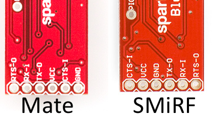
The difference between Mate and SMiRF all comes down to the pin-out of the six-pin header. If you flip each of the boards over, and look at the pin labels, this is what you’ll see:
Design Overview
The RN-42 and RN-41 are pin-for-pin compatible, so the schematic for each of these boards is the same. The only difference exists at the connector pin-out for the Mate and SMiRF. Click the image below to see a bigger view of the schematic (or click here to see it in PDF form).
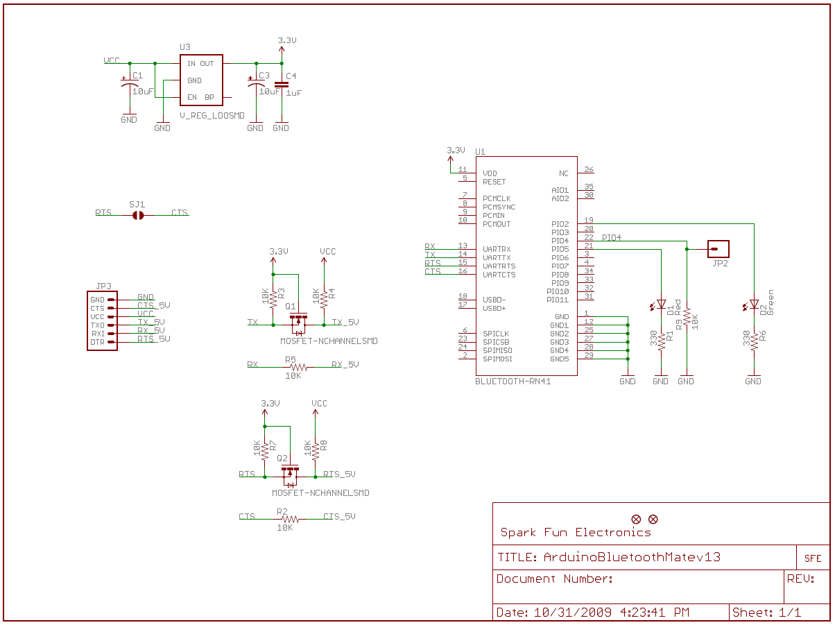
Key to the design are level shifting circuits between the RN-41/42’s serial pins, and the output header. The maximum operating voltage of the Roving Networks modules is 3.3V, so these enable a device operating at 5V (like an Arduino) to safely communicate with the Bluetooth modems. There is also a linear 3.3V regulator on the board, so a voltage from 3.3V to 6V can be used to supply power to the module.
The boards also include two LEDs. There’s a red “Stat” LED, and a green “Connect” LED. These can be used to determine what state the Bluetooth module is in.
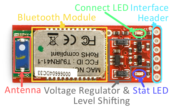
Finally, be aware of where the antenna is – give it some room to breathe. Don’t place it near any big chunks of metal or enclose it in a Faraday cage, and you should be just fine.
The Pinouts
Each of the four Bluetooth boards breaks out six pins. Four pins are devoted to the serial interface, and the other two are for power.
| Pin Label | Pin Function | Input, Output, Power? | Description |
|---|---|---|---|
| RTS-O | Request to send | Output | RTS is used for hardware flow control in some serial interfaces. This output is not critical for simple serial communication. |
| RX-I | Serial receive | Input | This pin receives serial data from another device. It should be connected to the TX of the other device. |
| TX-O | Serial transmit | Output | This pin sends serial data to another device. It should be connected to the RX of the other device. |
| VCC | Voltage supply | Power In | This voltage supply signal is routed through a 3.3V regulator, then routed to the Bluetooth module. It should range from 3.3V to 6V. |
| CTS-I | Clear to send | Input | CTS is another serial flow control signal. Like RTS, it's not required for most, simple serial interfaces. |
| GND | Ground | Power In | The 0V reference voltage, common to any other device connected to the Bluetooth modem. |
Powering the Modules
These Bluetooth devices are designed to work seamlessly in both 3.3V and 5V systems. The voltage supplied to the VCC/GND pins can be anywhere between 3.3V and 6V. Voltages on the input serial and control signals (RX-I and CTS-I) can be anywhere between 3.3V and 5V. The output signals (TX-O and RTS-O) will range from 0V for a LOW logic level, and VCC for a HIGH. That means if you power them at 6V, the TX and RTS signals will output up to 6V.
The current consumption of a modem depends on what it’s doing at the time. It can be as low as 0.026mA when the device is asleep, and as high as 50mA when data is being transmitted. This table from the datasheet provides some good estimates:

Connecting a device up to the Bluetooth modems is as easy as applying power and wiring up the serial RX and TX pins. What do we send over that serial interface, though? That’s where we need to look at the the firmware and the Bluetooth module’s operation modes.
Hardware Hookup
Assembly
Happily, most of the assembly on these modules is done for you; you don’t need to learn how to solder SMD components just yet. However, before you can begin using these Bluetooth modules, you’ll need to solder somethinginto the six plated-through-holes to form a solid electrical connection.
What you solder into the holes depends mostly on what you’re going to connect the device to. If you’ve got a Bluetooth Mate, and want to connect it directly to an Arduino Pro, you may want to throw a right-angle female header on there. Another good option, which makes the board breadboard-compatible, is male-headers. A third, ever-reliable option is to solder wires directly to the holes.
Connecting Everything Together
We need to connect the Bluetooth modems to devices that can send and receive serial signals. These are TTL-levelserial signals, make sure you don’t confuse that with RS-232! Voltages should be between 3.3V and 5V. There are loads of options here, for this tutorial we’ll use an Arduino.
Instead of connecting the Bluetooth modem to the Arduino’s lone hardware UART, we’ll use SoftwareSerial and connect the modem’s RX and TX pins to any of the Arduino’s free digital pins. This will help to avoid bus contention and will make sure the Bluetooth modem doesn’t receive any spurious data during a sketch upload. Here’s the connections we’ll make for the example code later in this tutorial:
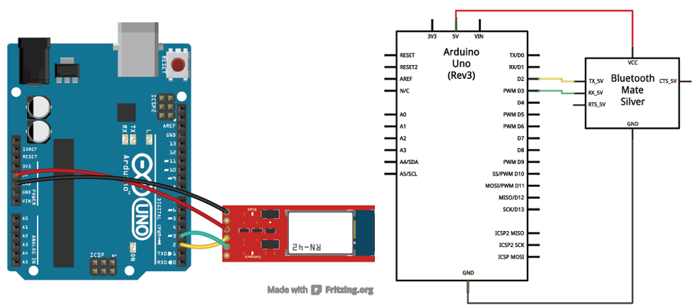
Note that this is a Bluetooth Mate shown in the Fritzing diagram, the BlueSMiRF will have a different pinout.
For Alamode


TX-O is connected to D2 of the Alamode (blue), RX-I is connected to D3 (white), GND goes to GND, and VCC goes to 5V. The CTS-I and RTS-O pins are left floating. The TX-O and RX-I pins could really be connected to any digital pin (besides 0 and 1), so if you need 2 and 3 for something else, feel free to move those around.
Half of the hardware hookup is done. We still need to create a wireless connection to another Bluetooth device. Before we can delve further into that, though, we need to understand more about the Bluetooth modem’s firmware.
Firmware Overview
A serial interface is all it takes to control these Bluetooth modules and send data through them. They act, essentially, like a data pipeline. Serial data that goes into the module (from the RX-I pin), is passed out the Bluetooth connection. Data coming in from the Bluetooth side is passed out the serial side (out the TX-O pin).
Establishing this data pipeline is a two step process. First, we need to connect something capable of sending and receiving serial data to the header of the Bluetooth modem. We achieved this in the Hardware Hookup phase by connecting an Arduino to the serial header, but any microcontroller with a UART could work. With the device connected we need to configure the serial port to work at the same baud rate the the modem is configured to – they default to 115200 bps (8-N-1).
Secondly, on the Bluetooth end of things, we need to establish a wireless connection between the modem and another Bluetooth device. The only stipulation here is the other Bluetooth device must support SPP (which most do). This connection involves a pairing process similar to connecting any other Bluetooth devices together. More on that later. Let’s talk a bit more about the serial interface.
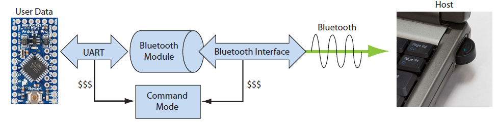
Data and Command Modes
Controlling the Bluetooth module and sending data through it are two very separate operations, but they’re both done via the serial interface. To differentiate between these two forms of data, the Bluetooth modules implement two different communication modes.
Command mode is used to configure the Bluetooth module. Characteristics like the device name, baud rate, PIN code, and data rate can be adjusted in command mode. This is also where action commands are sent to the module, which can tell it to connect to a device or scan for other modules.
In data mode, the Bluetooth module acts as a transparent data gateway. Any data received over the Bluetooth connection is routed out the module’s TX pin. And data sent to the module’s RX pin is piped out over the Bluetooth connection.
To enter command mode from data mode, the host controller needs to send a string of three $ symbols (
$$$).Configuration Timer
The configuration timer is the one obstacle to watch out for when entering command mode. The config timer begins counting as soon as the Bluetooth modem is turned on, and once it’s done counting, you’ll be unable to enter config mode unless you cycle power. By default the config timer is set to 60 seconds, however this can be adjusted, or even turned off (that’s the ticket!).
Deciphering the LEDs
There are two LEDs on the Bluetooth modems: a red one labeled “Stat”, and a green one labeled “Connect”. These help to indicate the status of the module. Never forget the importance of blinkies! The green LED will illuminate when a wireless connection is formed. The “Stat” LED can indicate that the module is in one of three states, depending on how fast it blinks:
| Mode | Stat Blink Rate | Notes |
|---|---|---|
| Configuration | 10 per second | Module is in config mode. |
| Startup/Config Timer | 2 per second | Module is not in config mode, but the configuration timer is still counting. |
| Discoverable/Inquiring/Idle | 1 per second | Not in config mode, and the config timer has run out. |
If you’re having trouble getting the module to enter configuration mode, make sure the timer hasn’t run out by checking for a very slow blink rate.
Bridge Mode
In bridge mode the BT is used to foward packet received over BT to Serial port and then the data is send over debug serial port of Alamode which is connected to the Rasberry PI serial port. This means that app running on the Rasberry pi will also receive the data transiting through the running Arduino Sketch on the ATMEL MCU. pretty Sweet!
/*
  Example Bluetooth Serial Passthrough Sketch
 by: Jim Lindblom
 SparkFun Electronics
 date: February 26, 2013
 license: Public domain

 This example sketch converts an RN-42 bluetooth module to
 communicate at 9600 bps (from 115200), and passes any serial
 data between Serial Monitor and bluetooth module.
 */
#include

int bluetoothTx = 2;  // TX-O pin of bluetooth mate, Arduino D2
int bluetoothRx = 3;  // RX-I pin of bluetooth mate, Arduino D3

SoftwareSerial bluetooth(bluetoothTx, bluetoothRx);

void setup()
{
  Serial.begin(9600);  // Begin the serial monitor at 9600bps

  bluetooth.begin(115200);  // The Bluetooth Mate defaults to 115200bps
  bluetooth.print("$");  // Print three times individually
  bluetooth.print("$");
  bluetooth.print("$");  // Enter command mode
  delay(100);  // Short delay, wait for the Mate to send back CMD
  bluetooth.println("U,9600,N");  // Temporarily Change the baudrate to 9600, no parity
  // 115200 can be too fast at times for NewSoftSerial to relay the data reliably
  bluetooth.begin(9600);  // Start bluetooth serial at 9600
}

void loop()
{
  if(bluetooth.available())  // If the bluetooth sent any characters
  {
    // Send any characters the bluetooth prints to the serial monitor
    Serial.print((char)bluetooth.read());
  }
  if(Serial.available())  // If stuff was typed in the serial monitor
  {
    // Send any characters the Serial monitor prints to the bluetooth
    bluetooth.print((char)Serial.read());
  }
  // and loop forever and ever!
}
Now you are good to use aRest.io with BluetoothMate !!
This sketch makes use of the SoftwareSerial library, which should be included with most of the recent versions of Arduino.
At the beginning of the sketch, the Arduino enters the command mode string and temporarily changes the Bluetooth modem’s baud rate to 9600 bps (using the
U,9600,N command). Remember this is temporary, so when power is cycled, the modem will default back to 115200 bps.
The loop of the sketch simply checks to see if either the Bluetooth modem or the Serial Monitor have sent any data to the Arduino. If so, it’ll relay the data sent from one device to the other.
Using the Passthrough Sketch
With the code uploaded, and everything hooked up accordingly, open up the Serial Monitor. Make sure the baud rate is set to 9600. Throughout this process you’ll have to fudge around with the dropdown menu to the left of the baud rate selection. It should initially be set to “No line ending”.
First, let’s enter command mode by typing
$$$, and click “Send”. You should see the Bluetooth modem respond with CMD, and you’ll notice the red Stat LED blinking much faster, this all indicates that the device is in command mode.
Once you’re in command mode, you’ll need to change the line ending dropdown to “Newline”. The basis of all this is that the RN-42 module expects a newline character after every command except for the command mode string. Annoying, but we’ll deal.
Using GET Commands
The GET commands are a good place to start using command mode, they’ll display settings, status, or other information that might be helpful. Try sending the “Display Basic Settings” command by typing “D”, and pressing “Send”. This will trigger a response from the Bluetooth modem that details, among other things, the baud rate settings, the name, and the address (BTA) of the device. The address is something you should take note of, it can either be identified from this command, or by taking a gander at the module’s label, next to the “MAC NO”. Each Bluetooth moule has a unique address which can’t be changed. Try sending the other get commands, and see what information you can retrieve from the modem.
Using SET Commands
After sending the “D” command, you may have noticed your Bluetooth modem has it’s own name, in addition to the address. Unlike the address, this name can be changed to whatever you’d like. By default it’ll be RN42-XXXX, where XXXX is the last four digits of the address. Let’s give a SET command a whirl. The is any collection of up to 20 characters. Think up a unique name, and assign it to your device. After sending the SN command, the modem should respond with an “AOK”. Now if you send the D command, you should see your new name listed next to the “BTName” setting.
SN, command is used to set the name, where 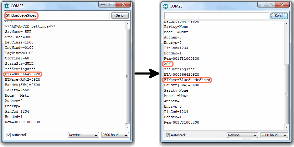
Be careful with the SET commands, only change something if you’re sure it won’t negatively affect the modem, or your ability to communicate with it. If you change something you don’t think you should have, send the
SF, 1 command to reset everything back to its factory default value. Another handy command, if you’re lazy like me, is ST,0, which turns the config timer off. Remember that any setting you modify will be saved to the Bluetooth modem’s memory, and will be retained upon loss of power.ACTION Commands
Finally, it’s time for some action. Among other things the Bluetooth modem’s ACTION commands can be used to find other Bluetooth devices, connect to them, and disconnect from them.
Begin by sending the inquiry scan command – parameter defines the number of seconds the modem will take to look for other modules. It’ll default to 10 if not defined. If you just type “I” and click send, the device should respond with a “Inquiry, COD=0”, and then after ten seconds it’ll respond with any Bluetooth modules it found. It will print their information as “BT address, BT name, COD” (COD is class of device).
I, – to search for other Bluetooth modules in range. The 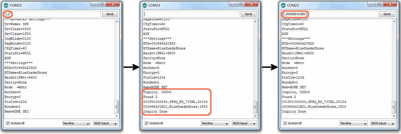
If the modem finds any modules, you can try sending the connect command –
C,
– to connect to one of them. The modem in the example above found two devices in range, by sending the C,000666421B01 command, we can attempt to connect to one of them.
After sending the connect command, the device will respond with “TRYING”, which will be followed by either “CONNECT failed” (the meaning of which should be pretty apparent) or the connection will be successful! After a successful connection we immediately enter data mode, and the modem becomes a pipeline. Any characters sent from one Bluetooth device will be sent to the other, and vice-versa. To disconnect, you’ll need to re-enter command mode (don’t forget to set to “No new line”), and send the “K,” command (with Newline selected, bleh).
There are a lot of other commands to explore! Thumb through the User’s Manual and familiarize yourself with all of the power at your Bluetooth modems’s fingertips!
Connecting From Another Device
In the example code section we attempted to connect to a device from the Bluetooth modem, but what if you wanted to initiate the connection from another Bluetooth device? This process varies by operating system and device, but most of the steps involved are pretty similar.
If your device (computer, phone, etc.) doesn’t already have an Bluetooth modem, you’ll need to connect an external module to it. The Bluetooth USB Module works for any computer with an available USB slot.
Connecting to the Modem in Windows
Go to the Control Panel and navigate to the Devices and Printers window. In the top-left section of that window, there should be an Add a device button. Click that.
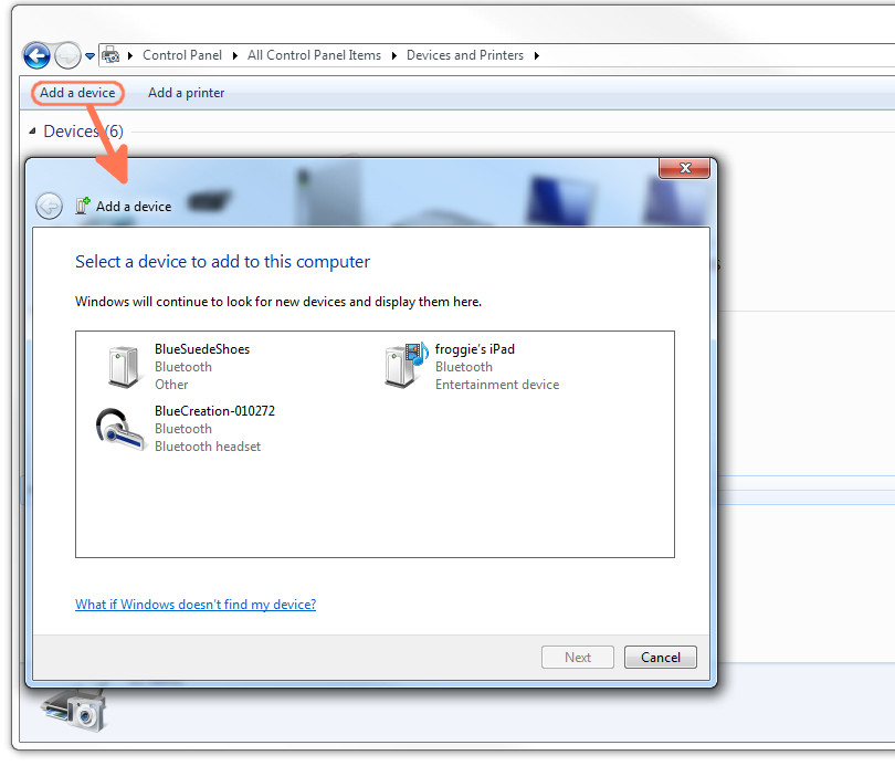
When the Add a device window opens your computer’s Bluetooth module should automatically search for any in-range, available Bluetooth devices. Those it finds should show up in the window (give the window a few seconds to search).
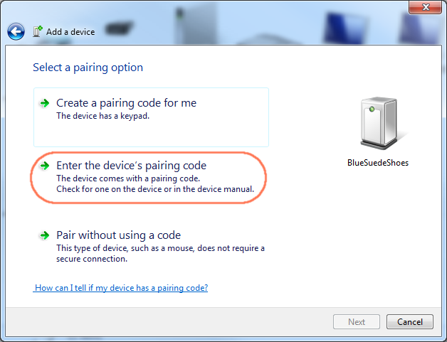
If you see your device in this window, double-click it to initiate a connection. You’ll then be presented with the Select a pairing option window. Since the modems don’t have an attached keypad, select the Enter the device’s pairing code option.
On the next window, enter 1234 as the PIN code. This is the default PIN value for every RN-42 and RN-41.
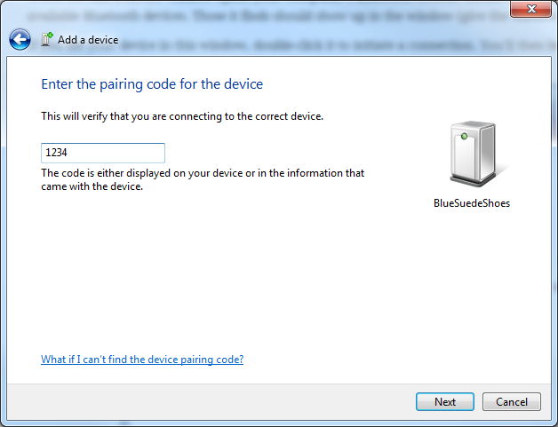
Windows will take a few moments to install drivers for your device. Once it’s done, it’ll pop up a notification to let you know that your device is ready to use!
But how do you actually use it? You’ll need to open up a terminal emulator (check out our Serial Terminal Basics tutorial for help!). When Windows installed drivers for your new Bluetooth device, it created a new COM port for it. Opening up your device manager, and looking in the “Ports (COM & LPT)” tree, you’ll find a new port named “Standard Serial over Bluetooth link (COM##)” (there may be two of them).
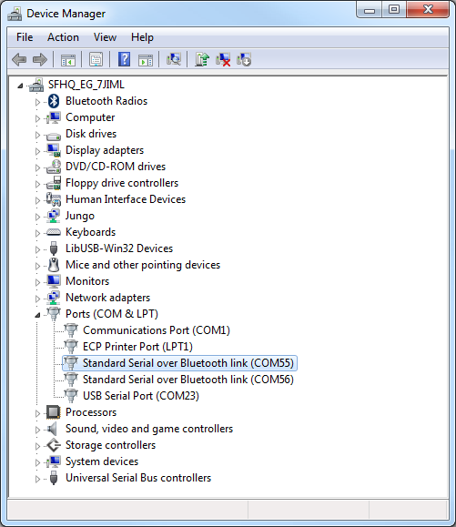
To open up a connection between the Bluetooth devices, open up a terminal to that COM port at 9600 bps (8-N-1). (If you see two ports, try the lower number first). When the terminal opens up, your Bluetooth modem’s green connect LED should light up. Connection successful!
If you have the sketch from the last example (the serial passthrough) still loaded up on your Arduino, you can open up a second terminal window to communicate between devices.
If you’re within the config timer window (cycle power on the modem if you’re not), you can even remotely enter command mode by sending the “$$$” string. Now you can remotely alter the settings of your Bluetooth modem. Nifty!
If your using a Mac, Linux, or even a smartphone, pairing and connecting should involve a similar process. If authentication is required, you’ll want to use the PIN-code option, and enter the default PIN of “1234”. Open up a serial terminal emulator – Terminal or CoolTerm on Mac OSX, a variety of apps are available for smartphones – to initiate the connection and start passing data.
aRest API Mode
The aREST framework was created to give RESTful interface to several embedded boards & platforms. In a nutshell, the library allows you to send commands to a given board running aREST, provoke an action (or just get some data), and send data back in a JSON container.
For example, to set the state of pin 6 to HIGH on an Arduino board running aREST, connected to your local network via Ethernet, and with the IP address 192.168.1.101, you would send the command:
192.168.1.101/digital/6/1
It’s that simple. As an answer, the board will then send:
{“message”: “Pin D6 set to 1?, “id”: “1”, “name”: “arduino”, “connected”: true}
This makes aREST really easy to use for your connected project. You don’t have to change the code on your embedded boards anymore: set it once, and then interact with your boards using a RESTful interface.
let's modify aRest to support SoftwareSerial
edit aREST.h and merge with following version
/*
  aREST Library for Arduino
  See the README file for more details.

  Written in 2014 by Marco Schwartz under a GPL license.
  Version 1.9.8
  Changelog:

  Version 1.9.8: Added support for ESP8266 chip
  Version 1.9.7: Added support for Arduino 1.6.2
  Version 1.9.6: Added support for float variables for Arduino Mega
  Version 1.9.5: Added compatibility with Arduino IDE 1.5.8
  Version 1.9.4: Bug fixes & added support for configuring analog pints as digital outputs
  Version 1.9.3: Added description of available variables for the /id and / routes
  Version 1.9.2: Added compatibility with the Arduino WiFi library
  Version 1.9.1: Added compatibility with CORS
  Version 1.9: New speedup of the library (answers 2x faster in HTTP compared to version 1.8)
  Version 1.8: Speedup of the library (answers 2.5x faster with the CC3000 WiFi chip)
  Version 1.7.5: Reduced memory footprint of the library
  Version 1.7.4: Added a function to read all analog & digital inputs at once
  Version 1.7.3: Added LIGHTWEIGHT mode to only send limited data back
  Version 1.7.2: Added possibility to assign a status pin connected to a LED
  Version 1.7.1: Added possibility to change number of exposed variables & functions
  Version 1.7: Added compatibility with the Arduino Due & Teensy 3.x
  Version 1.6: Added compatibility with the Arduino Yun

  Version 1.5: Size reduction, and added compatibility with Adafruit BLE

  Version 1.4: Added authentification with API key

  Version 1.3: Added support for the Ethernet shield

  Version 1.2: Added support of Serial communications

  Version 1.1: Added variables & functions support

  Version 1.0: First working version of the library
*/

#ifndef aRest_h
#define aRest_h

// Include Arduino header
#include "Arduino.h"


#include

// Using ESP8266 ?
#if defined(ESP8266)
#include "stdlib_noniso.h"
#endif

// Which board?
#if defined(__AVR_ATmega1280__) || defined(__AVR_ATmega2560__) || defined(CORE_WILDFIRE) || defined(ESP8266)
#define NUMBER_ANALOG_PINS 16
#define NUMBER_DIGITAL_PINS 54
#define OUTPUT_BUFFER_SIZE 2000
#elif defined(__AVR_ATmega328P__) && !defined(ADAFRUIT_CC3000_H)
#define NUMBER_ANALOG_PINS 6
#define NUMBER_DIGITAL_PINS 14
#define OUTPUT_BUFFER_SIZE 350
#elif defined(ADAFRUIT_CC3000_H)
#define NUMBER_ANALOG_PINS 6
#define NUMBER_DIGITAL_PINS 14
#define OUTPUT_BUFFER_SIZE 275
#else
#define NUMBER_ANALOG_PINS 6
#define NUMBER_DIGITAL_PINS 14
#define OUTPUT_BUFFER_SIZE 350
#endif

// Size of name & ID
#define NAME_SIZE 20
#define ID_SIZE 10

// Debug mode
#ifndef DEBUG_MODE
#define DEBUG_MODE 0
#endif

// Use light answer mode
#ifndef LIGHTWEIGHT
#define LIGHTWEIGHT 0
#endif

// Default number of max. exposed variables
#ifndef NUMBER_VARIABLES
  #if defined(__AVR_ATmega1280__) || defined(__AVR_ATmega2560__) || defined(CORE_WILDFIRE) || defined(ESP8266)
  #define NUMBER_VARIABLES 10
  #else
  #define NUMBER_VARIABLES 5
  #endif
#endif

// Default number of max. exposed functions
#ifndef NUMBER_FUNCTIONS
  #if defined(__AVR_ATmega1280__) || defined(__AVR_ATmega2560__) || defined(CORE_WILDFIRE) || defined(ESP8266)
  #define NUMBER_FUNCTIONS 10
  #else
  #define NUMBER_FUNCTIONS 5
  #endif
#endif

class aREST {

public:

aREST() {

  command = 'u';
  pin_selected = false;

  status_led_pin = 255;
  state = 'u';

}

// Set status LED
void set_status_led(uint8_t pin){

  // Set variables
  status_led_pin = pin;

  // Set pin as output
  pinMode(status_led_pin,OUTPUT);
}

// Glow status LED
void glow_led() {

  if(status_led_pin != 255){
    unsigned long i = millis();
    int j = i % 4096;
    if (j > 2048) { j = 4096 - j;}
      analogWrite(status_led_pin,j/8);
    }
}

// Send HTTP headers for Ethernet & WiFi
void send_http_headers(){

  addToBuffer(F("HTTP/1.1 200 OK\r\nAccess-Control-Allow-Origin: *\r\nAccess-Control-Allow-Methods: POST, GET, PUT, OPTIONS\r\nContent-Type: application/json\r\nConnection: close\r\n\r\n"));
}

// Reset variables after a request
void reset_status() {
  answer = "";
  command = 'u';
  pin_selected = false;
  state = 'u';
  arguments = "";

  index = 0;
  //memset(&buffer[0], 0, sizeof(buffer));

}

// Handle request with the Adafruit CC3000 WiFi library
#ifdef ADAFRUIT_CC3000_H
void handle(Adafruit_CC3000_ClientRef& client) {

  if (client.available()) {

    // Handle request
    handle_proto(client,true,0);

    // Answer
    sendBuffer(client,32,20);
    client.stop();

    // Reset variables for the next command
    reset_status();
  }
}

// Handle request with the Arduino Yun
#elif defined(_YUN_CLIENT_H_)
void handle(YunClient& client) {

  if (client.available()) {

    // Handle request
    handle_proto(client,false,0);

    // Answer
    sendBuffer(client,25,10);
    client.stop();

    // Reset variables for the next command
    reset_status();
  }
}

// Handle request with the Adafruit BLE board
#elif defined(_ADAFRUIT_BLE_UART_H_)
void handle(Adafruit_BLE_UART& serial) {

  if (serial.available()) {

    // Handle request
    handle_proto(serial,false,0);

    // Answer
    sendBuffer(serial,100,1);

    // Reset variables for the next command
    reset_status();
  }
}

// Handle request for the Arduino Ethernet shield
#elif defined(ethernet_h)
void handle(EthernetClient& client){

  if (client.available()) {

    // Handle request
    handle_proto(client,true,0);

    // Answer
    sendBuffer(client,50,0);
    client.stop();

    // Reset variables for the next command
    reset_status();
  }
}

// Handle request for the ESP8266 chip
#elif defined(ESP8266)
void handle(WiFiClient& client){

  if (client.available()) {

    if (DEBUG_MODE) {Serial.println("Request received");}

    // Handle request
    handle_proto(client,true,0);

    // Answer
    sendBuffer(client,0,0);
    client.stop();

    // Reset variables for the next command
    reset_status();
  }
}

// Handle request for the Arduino WiFi shield
#elif defined(WiFi_h)
void handle(WiFiClient& client){

  if (client.available()) {

    if (DEBUG_MODE) {Serial.println("Request received");}

    // Handle request
    handle_proto(client,true,0);

    // Answer
    sendBuffer(client,50,1);
    client.stop();

    // Reset variables for the next command
    reset_status();
  }
}

#elif defined(CORE_TEENSY)
// Handle request on the Serial port
void handle(usb_serial_class& serial){

  if (serial.available()) {

    // Handle request
    handle_proto(serial,false,1);

    // Answer
    sendBuffer(serial,25,1);

    // Reset variables for the next command
    reset_status();
  }
}

#elif defined(__AVR_ATmega32U4__)
// Handle request on the Serial port
void handle(Serial_& serial){

  if (serial.available()) {

    // Handle request
    handle_proto(serial,false,1);

    // Answer
    sendBuffer(serial,25,1);

    // Reset variables for the next command
    reset_status();
  }
}

#elif defined(__RN41__)

// Handle request on the SoftwareSerial port
void handle(SoftwareSerial & client){

  if (client.available()) {

    // Handle request
    handle_proto(client,false,1);

    // Answer
    sendBuffer(client,25,1);

    // Reset variables for the next command
    reset_status();
  }
}
#else
// Handle request on the Serial port
void handle(HardwareSerial& serial){

  if (serial.available()) {

    // Handle request
    handle_proto(serial,false,1);

    // Answer
    sendBuffer(serial,25,1);

    // Reset variables for the next command
    reset_status();
  }
}
#endif

void handle(char * string) {

  // Process String
  handle_proto(string);

  // Reset variables for the next command
  reset_status();
}

void handle_proto(char * string) {
  // Check if there is data available to read
  for (int i = 0; i < strlen(string); i++){

    char c = string[i];
    answer = answer + c;

    // Process data
    process(c);

  }

  // Send command
  send_command(false);
}

template <typename T>
void handle_proto(T& serial, bool headers, uint8_t read_delay)
{

  // Check if there is data available to read
  while (serial.available()) {

    // Get the server answer
    char c = serial.read();
    delay(read_delay);
    answer = answer + c;
    //if (DEBUG_MODE) {Serial.print(c);}

    // Process data
    process(c);

   }

   // Send command
   send_command(headers);
}

void process(char c){

  // Check if we are receveing useful data and process it
  if ((c == '/' || c == '\r') && state == 'u') {

      if (DEBUG_MODE) {Serial.println(answer);}

      // If the command is mode, and the pin is already selected
      if (command == 'm' && pin_selected && state == 'u') {

        // Get state
        state = answer[0];

     }

     // If a digital command has been received, process the data accordingly
     if (command == 'd' && pin_selected && state == 'u') {

       // If it's a read command, read from the pin and send data back
       if (answer[0] == 'r') {state = 'r';}

       // If not, get value we want to apply to the pin
       else {value = answer.toInt(); state = 'w';}
     }

     // If analog command has been selected, process the data accordingly
     if (command == 'a' && pin_selected && state == 'u') {

       // If it's a read, read from the correct pin
       if (answer[0] == 'r') {state = 'r';}

       // Else, write analog value
       else {value = answer.toInt(); state = 'w';}
     }

     // If the command is already selected, get the pin
     if (command != 'u' && pin_selected == false) {

       // Get pin
       if (answer[0] == 'A') {
         pin = 14 + answer[1] - '0';
       }
       else {
         pin = answer.toInt();
       }
       if (DEBUG_MODE) {
        Serial.print("Selected pin: ");
        Serial.println(pin);
       }
       pin_selected = true;

       // Nothing more ?
       if ((answer[1] != '/' && answer[2] != '/')
        || (answer[1] == ' ' && answer[2] == '/')
        || (answer[2] == ' ' && answer[3] == '/')) {

        // Nothing more & digital ?
        if (command == 'd') {

          // Read all digital ?
          if (answer[0] == 'a') {state = 'a';}

          // Save state & end there
          else {state = 'r';}
        }

       // Nothing more & analog ?
       if (command == 'a') {

         // Read all analog ?
         if (answer[0] == 'a') {state = 'a';}

         // Save state & end there
         else {state = 'r';}
       }
     }

   }

     // Digital command received ?
     if (answer.startsWith("digital")) {command = 'd';}

     // Mode command received ?
     if (answer.startsWith("mode")) {command = 'm';}

     // Analog command received ?
     if (answer.startsWith("analog")) {command = 'a';}

     // Variable or function request received ?
     if (command == 'u') {

       // Check if variable name is in int array
       for (uint8_t i = 0; i < variables_index; i++){
         if(answer.startsWith(int_variables_names[i])) {

           // End here
           pin_selected = true;
           state = 'x';

           // Set state
           command = 'v';
           value = i;
         }
       }

       // Check if variable name is in float array (Mega & ESP8266 only)
       #if defined(__AVR_ATmega1280__) || defined(__AVR_ATmega2560__) || defined(ESP8266) || defined(CORE_WILDFIRE)
       for (uint8_t i = 0; i < float_variables_index; i++){
         if(answer.startsWith(float_variables_names[i])) {

           // End here
           pin_selected = true;
           state = 'x';

           // Set state
           command = 'l';
           value = i;
         }
       }
       #endif

       // Check if variable name is in float array (Mega & ESP8266 only)
       #if defined(__AVR_ATmega1280__) || defined(__AVR_ATmega2560__) || defined(ESP8266) || defined(CORE_WILDFIRE)
       for (uint8_t i = 0; i < string_variables_index; i++){
         if(answer.startsWith(string_variables_names[i])) {

           // End here
           pin_selected = true;
           state = 'x';

           // Set state
           command = 's';
           value = i;
         }
       }
       #endif

       // Check if function name is in array
       for (uint8_t i = 0; i < functions_index; i++){
         if(answer.startsWith(functions_names[i])) {

           // End here
           pin_selected = true;
           state = 'x';

           // Set state
           command = 'f';
           value = i;

           // Get command
           arguments = "";
           uint8_t header_length = strlen(functions_names[i]);
           if (answer.substring(header_length, header_length + 1) == "?") {
             uint8_t footer_start = answer.length();
             if (answer.endsWith(" HTTP/"))
               footer_start -= 6; // length of " HTTP/"
             arguments = answer.substring(header_length + 8, footer_start);
           }
         }
       }

       // If the command is "id", return device id, name and status
       if ( (answer[0] == 'i' && answer[1] == 'd') ){

           // Set state
           command = 'i';

           // End here
           pin_selected = true;
           state = 'x';
       }

       if (answer[0] == ' '){

           // Set state
           command = 'r';

           // End here
           pin_selected = true;
           state = 'x';
       }

       // Check the type of HTTP request
       // if (answer.startsWith("GET")) {method = "GET";}
       // if (answer.startsWith("POST")) {method = "POST";}
       // if (answer.startsWith("PUT")) {method = "PUT";}
       // if (answer.startsWith("DELETE")) {method = "DELETE";}

       // if (DEBUG_MODE && method != "") {
       //  Serial.print("Selected method: ");
       //  Serial.println(method);
       // }

     }

     answer = "";
    }
}

bool send_command(bool headers) {

   if (DEBUG_MODE) {
     Serial.println(F("Sending command"));
     Serial.print(F("Command: "));
     Serial.println(command);
     Serial.print(F("State: "));
     Serial.println(state);
     Serial.print(F("State of buffer at the start: "));
     Serial.println(buffer);
   }

   // Start of message
   if (headers && command != 'r') {send_http_headers();}

   // Mode selected
   if (command == 'm'){

     // Send feedback to client
     if (!LIGHTWEIGHT){
       addToBuffer(F("{\"message\": \"Pin D"));
       addToBuffer(pin);
     }

     // Input
     if (state == 'i'){

      // Set pin to Input
      pinMode(pin,INPUT);

      // Send feedback to client
      if (!LIGHTWEIGHT){addToBuffer(F(" set to input\", "));}
     }

     // Output
     if (state == 'o'){

       // Set to Output
       pinMode(pin,OUTPUT);

       // Send feedback to client
       if (!LIGHTWEIGHT){addToBuffer(F(" set to output\", "));}
     }

   }

   // Digital selected
   if (command == 'd') {
     if (state == 'r'){

       // Read from pin
       value = digitalRead(pin);

       // Send answer
       if (LIGHTWEIGHT){addToBuffer(value);}
       else {
        addToBuffer(F("{\"return_value\": "));
        addToBuffer(value);
        addToBuffer(F(", "));
      }
     }

     #if !defined(__AVR_ATmega32U4__) || !defined(ADAFRUIT_CC3000_H)
     if (state == 'a') {
       if (!LIGHTWEIGHT) {addToBuffer(F("{"));}

       for (uint8_t i = 0; i < NUMBER_DIGITAL_PINS; i++) {

         // Read analog value
         value = digitalRead(i);

         // Send feedback to client
         if (LIGHTWEIGHT){
           addToBuffer(value);
           addToBuffer(F(","));
         }
         else {
           addToBuffer(F("\"D"));
           addToBuffer(i);
           addToBuffer(F("\": "));
           addToBuffer(value);
           addToBuffer(F(", "));
         }
     }
    }
    #endif

     if (state == 'w') {

       // Apply on the pin
       digitalWrite(pin,value);

       // Send feedback to client
       if (!LIGHTWEIGHT){
        addToBuffer(F("{\"message\": \"Pin D"));
        addToBuffer(pin);
        addToBuffer(F(" set to "));
        addToBuffer(value);
        addToBuffer(F("\", "));
       }
     }
   }

   // Analog selected
   if (command == 'a') {
     if (state == 'r'){

       // Read analog value
       value = analogRead(pin);

       // Send feedback to client
       if (LIGHTWEIGHT){addToBuffer(value);}
       else {
        addToBuffer(F("{\"return_value\": "));
        addToBuffer(value);
        addToBuffer(F(", "));
       }
     }
     #if !defined(__AVR_ATmega32U4__)
     if (state == 'a') {
       if (!LIGHTWEIGHT) {addToBuffer(F("{"));}

       for (uint8_t i = 0; i < NUMBER_ANALOG_PINS; i++) {

         // Read analog value
         value = analogRead(i);

         // Send feedback to client
         if (LIGHTWEIGHT){
           addToBuffer(value);
           addToBuffer(F(","));
         }
         else {
           addToBuffer(F("\"A"));
           addToBuffer(i);
           addToBuffer(F("\": "));
           addToBuffer(value);
           addToBuffer(F(", "));
         }
     }
   }
   #endif
   if (state == 'w') {

     // Write output value
     analogWrite(pin,value);

     // Send feedback to client
     addToBuffer(F("{\"message\": \"Pin D"));
     addToBuffer(pin);
     addToBuffer(F(" set to "));
     addToBuffer(value);
     addToBuffer(F("\", "));

   }
  }

  // Variable selected
  if (command == 'v') {

       // Send feedback to client
       if (LIGHTWEIGHT){addToBuffer(*int_variables[value]);}
       else {
        addToBuffer(F("{\""));
        addToBuffer(int_variables_names[value]);
        addToBuffer(F("\": "));
        addToBuffer(*int_variables[value]);
        addToBuffer(F(", "));
       }
  }

  // Float ariable selected (Mega only)
  #if defined(__AVR_ATmega1280__) || defined(__AVR_ATmega2560__) || defined(ESP8266) || defined(CORE_WILDFIRE)
  if (command == 'l') {

       // Send feedback to client
       if (LIGHTWEIGHT){addToBuffer(*float_variables[value]);}
       else {
        addToBuffer(F("{\""));
        addToBuffer(float_variables_names[value]);
        addToBuffer(F("\": "));
        addToBuffer(*float_variables[value]);
        addToBuffer(F(", "));
       }
  }
  #endif

  // String variable selected (Mega & ESP8266 only)
  #if defined(__AVR_ATmega1280__) || defined(__AVR_ATmega2560__) || defined(ESP8266) || defined(CORE_WILDFIRE)
  if (command == 's') {

       // Send feedback to client
       if (LIGHTWEIGHT){addToBuffer(*string_variables[value]);}
       else {
        addToBuffer(F("{\""));
        addToBuffer(string_variables_names[value]);
        addToBuffer(F("\": \""));
        addToBuffer(*string_variables[value]);
        addToBuffer(F("\", "));
       }
  }
  #endif

  // Function selected
  if (command == 'f') {

    // Execute function
    uint8_t result = functions[value](arguments);

    // Send feedback to client
    if (!LIGHTWEIGHT) {
     addToBuffer(F("{\"return_value\": "));
     addToBuffer(result);
     addToBuffer(F(", "));
     //addToBuffer(F(", \"message\": \""));
     //addToBuffer(functions_names[value]);
     //addToBuffer(F(" executed\", "));
    }
  }

  if (command == 'r') {
    root_answer();
  }

  if (command == 'i') {
    if (LIGHTWEIGHT) {addToBuffer(id);}
    else {
      addToBuffer(F("{"));
    }
  }

   // End of message
   if (LIGHTWEIGHT){
     addToBuffer(F("\r\n"));
   }

   else {

     if (command != 'r') {
      addToBuffer(F("\"id\": \""));
       addToBuffer(id);
       addToBuffer(F("\", \"name\": \""));
       addToBuffer(name);
       addToBuffer(F("\", \"connected\": true}\r\n"));
     }
   }

   if (DEBUG_MODE) {
     Serial.print(F("State of buffer at the end: "));
     Serial.println(buffer);
   }

   // End here
   return true;
}

virtual void root_answer() {
  if (LIGHTWEIGHT) {addToBuffer(id);}
    else {
      addToBuffer(F("{\"variables\": {"));

      // Int variables
      if (variables_index > 0){

        for (uint8_t i = 0; i < variables_index-1; i++){
          addToBuffer(F("\""));
          addToBuffer(int_variables_names[i]);
          addToBuffer(F("\": "));
          addToBuffer(*int_variables[i]);
          addToBuffer(F(", "));
        }
        addToBuffer(F("\""));
        addToBuffer(int_variables_names[variables_index-1]);
        addToBuffer(F("\": "));
        addToBuffer(*int_variables[variables_index-1]);
        addToBuffer(F("}, "));
      }
      else {
        addToBuffer(F(" }, "));
      }

    }
}

void variable(char * variable_name, int *variable){

  int_variables[variables_index] = variable;
  int_variables_names[variables_index] = variable_name;
  variables_index++;

}

// Float variables (Mega & ESP only)
#if defined(__AVR_ATmega1280__) || defined(__AVR_ATmega2560__) || defined(ESP8266) || defined(CORE_WILDFIRE)
void variable(char * variable_name, float *variable){

  float_variables[float_variables_index] = variable;
  float_variables_names[float_variables_index] = variable_name;
  float_variables_index++;

}
#endif

// String variables (Mega & ESP only)
#if defined(__AVR_ATmega1280__) || defined(__AVR_ATmega2560__) || defined(ESP8266) || defined(CORE_WILDFIRE)
void variable(char * variable_name, String *variable){

  string_variables[string_variables_index] = variable;
  string_variables_names[string_variables_index] = variable_name;
  string_variables_index++;

}
#endif

void function(char * function_name, int (*f)(String)){

  functions_names[functions_index] = function_name;
  functions[functions_index] = f;
  functions_index++;
}

// Set device ID
void set_id(char *device_id){

  strcpy(id,device_id);
}

// Set device name
void set_name(char *device_name){

  strcpy(name, device_name);
}

// Set device name
void set_name(String device_name){

  device_name.toCharArray(name, NAME_SIZE);
}

// Set device ID
void set_id(String device_id){

  device_id.toCharArray(id, NAME_SIZE);
}

// Add to output buffer
void addToBuffer(char * toAdd){

  if (DEBUG_MODE) {
    Serial.print(F("Added to buffer: "));
    Serial.println(toAdd);
  }

  for (int i = 0; i < strlen(toAdd); i++){
    buffer[index+i] = toAdd[i];
  }
  index = index + strlen(toAdd);
}

// Add to output buffer
#if defined(__AVR_ATmega1280__) || defined(__AVR_ATmega2560__) || defined(ESP8266) || defined(CORE_WILDFIRE)
void addToBuffer(String toAdd){

  if (DEBUG_MODE) {
    Serial.print(F("Added to buffer: "));
    Serial.println(toAdd);
  }

  for (int i = 0; i < toAdd.length(); i++){
    buffer[index+i] = toAdd[i];
  }
  index = index + toAdd.length();
}
#endif

// Add to output buffer
void addToBuffer(uint16_t toAdd){

  char number[10];
  itoa(toAdd,number,10);

  addToBuffer(number);
}

// Add to output buffer
void addToBuffer(int toAdd){

  char number[10];
  itoa(toAdd,number,10);

  addToBuffer(number);
}

// Add to output buffer (Mega & ESP only)
#if defined(__AVR_ATmega1280__) || defined(__AVR_ATmega2560__) || defined(ESP8266) || defined(CORE_WILDFIRE)
void addToBuffer(float toAdd){

  char number[10];
  dtostrf(toAdd, 5, 2, number);

  addToBuffer(number);
}
#endif

// Add to output buffer
void addToBuffer(const __FlashStringHelper *toAdd){

  // if (DEBUG_MODE) {
  //   Serial.print(F("Added to buffer: "));
  //   Serial.println(toAdd);
  // }

  uint8_t idx = 0;

  PGM_P p = reinterpret_cast<PGM_P>(toAdd);

  while (1) {
    unsigned char c = pgm_read_byte(p++);
    if (c == 0) break;
    buffer[index + idx] = c;
    idx++;
  }
  index = index + idx;
}

template <typename T>
void sendBuffer(T& client, uint8_t chunkSize, uint8_t wait_time) {

  if (DEBUG_MODE) {
    Serial.print(F("Buffer size: "));
    Serial.println(index);
  }

  // Send all of it
  if (chunkSize == 0) {
    client.print(buffer);
  }

  // Send chunk by chunk
  else {

    // Max iteration
    uint8_t max_iteration = (int)(index/chunkSize) + 1;

    // Send data
    for (uint8_t i = 0; i < max_iteration; i++) {
      char intermediate_buffer[chunkSize+1];
      memcpy(intermediate_buffer, buffer + i*chunkSize, chunkSize);
      intermediate_buffer[chunkSize] = '\0';

      // Send intermediate buffer
      #ifdef ADAFRUIT_CC3000_H
      client.fastrprint(intermediate_buffer);
      #else
      client.print(intermediate_buffer);
      #endif

      // Wait for client to get data
      delay(wait_time);

      if (DEBUG_MODE) {
        Serial.print(F("Sent buffer: "));
        Serial.println(intermediate_buffer);
      }
    }
  }

    // Reset the buffer
    resetBuffer();
}

char * getBuffer() {
  return buffer;
}

void resetBuffer(){
  memset(&buffer[0], 0, sizeof(buffer));
}


private:
  String answer;
  char command;
  uint8_t pin;
  char state;
  uint16_t value;
  boolean pin_selected;

  //char * method;

  char name[NAME_SIZE];
  char id[ID_SIZE];
  String arguments;

  // Output uffer
  char buffer[OUTPUT_BUFFER_SIZE];
  uint16_t index;

  // Status LED
  uint8_t status_led_pin;

  // Int variables arrays
  uint8_t variables_index;
  int * int_variables[NUMBER_VARIABLES];
  char * int_variables_names[NUMBER_VARIABLES];

  // Float variables arrays (Mega & ESP8266 only)
  #if defined(__AVR_ATmega1280__) || defined(__AVR_ATmega2560__) || defined(ESP8266) || defined(CORE_WILDFIRE)
  uint8_t float_variables_index;
  float * float_variables[NUMBER_VARIABLES];
  char * float_variables_names[NUMBER_VARIABLES];
  #endif

  // String variables arrays (Mega & ESP8266 only)
  #if defined(__AVR_ATmega1280__) || defined(__AVR_ATmega2560__) || defined(ESP8266) || defined(CORE_WILDFIRE)
  uint8_t string_variables_index;
  String * string_variables[NUMBER_VARIABLES];
  char * string_variables_names[NUMBER_VARIABLES];
  #endif

  // Functions array
  uint8_t functions_index;
  int (*functions[NUMBER_FUNCTIONS])(String);
  char * functions_names[NUMBER_FUNCTIONS];

};

#endif
/*
  Example Bluetooth Serial aRest Sketch
 by: Thomas Younsi
 date: August 7, 2015
 license: Public domain

 This example sketch converts an RN-42 bluetooth module to
 communicate at 9600 bps (from 115200), and Handle REST calls
 send over bluetooth.
 */
#define __RN41__ 1

#include <SoftwareSerial.h>
// Create aREST instance
aREST rest = aREST();
// Variables to be exposed to the API
int temperature;
int humidity;
int led = 13;


#include
int bluetoothTx = 2;  // TX-O pin of bluetooth mate, Arduino D2
int bluetoothRx = 3;  // RX-I pin of bluetooth mate, Arduino D3

SoftwareSerial bluetooth(bluetoothTx, bluetoothRx);

void setup()
{
  // initialize the digital pin as an output.
  pinMode(led, OUTPUT);

  // Start Serial
#ifdef BRIDGE
  Serial.begin(9600);  // Begin the serial monitor at 9600bps
#else
  Serial.begin(115200);
#endif

  bluetooth.begin(115200);  // The Bluetooth Mate defaults to 115200bps
  bluetooth.print("$");  // Print three times individually
  bluetooth.print("$");
  bluetooth.print("$");  // Enter command mode
  delay(100);  // Short delay, wait for the Mate to send back CMD
  bluetooth.println("U,9600,N");  // Temporarily Change the baudrate to 9600, no parity
  // 115200 can be too fast at times for NewSoftSerial to relay the data reliably
  bluetooth.begin(9600);  // Start bluetooth serial at 9600

  // Init variables and expose them to REST API
  temperature = 24;
  humidity = 40;
  rest.variable("temperature",&temperature);
  rest.variable("humidity",&humidity);
  // Function to be exposed
  rest.function("led",ledControl);
  // Give name and ID to device
  rest.set_id("008");
  rest.set_name("ble_drake");
}

void loop()
{
  if(bluetooth.available())  // If the bluetooth sent any characters
  {
    // Handle REST calls send over bluetooth
    rest.handle(bluetooth);

    // Send any characters the bluetooth prints to the serial monitor
    //Serial.print((char)bluetooth.read());
  }
#ifdef BRIDGE
  if(Serial.available())  // If stuff was typed in the serial monitor
  {
    // Send any characters the Serial monitor prints to the bluetooth
    bluetooth.print((char)Serial.read());
  }
#endif
  // and loop forever and ever!
}


// Custom function accessible by the REST API
int ledControl(String command)
{
  // Get state from command
  int state = command.toInt();

  digitalWrite(led,state);
  return 1;
}
Android Client TODO
iOS Client TODO
Resources and Going Further
Hopefully this tutorial has prepared you for an exciting foray into the world of wireless communication. Now that you have a good idea of how to command these Bluetooth modems, and connect them to other devices, the rest is up to you. How are you going to make use of your pleasant lack of wire? Go hit the airwaves!
No comments:
Post a Comment